 Sign In
Pages
Category
 AI Tools
 Health
 Math
Math Everyday Life
 Finance
 Physics
 Chemistry
 Statistics
 Construction
 Pets
Pets Time & Date
Follow Us On:
Pages
Category
Follow Us On:
The calculator will determine the voltage drop, its percentage, and the resistivity of any wire piece based on the NEC or provided wire resistivity data.
Related
Calculate the overall drop in voltage for DC and AC circuits using this voltage drop calculator. It uses NEC and wire resistance equations for power loss across a load in single-phase and three-phase systems, and provides the actual potential drop across the circuit. Additionally, the calculator can provide the wire cross-sectional area, resistance, and voltage across terminals.
Voltage drop is the overall loss of voltage due to the internal impedance of the circuit.
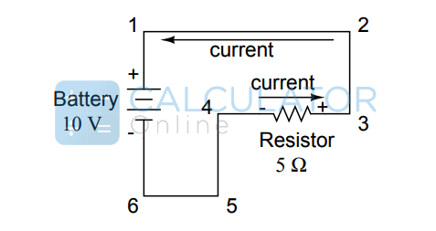
In the figure above, a voltage is applied to a circuit containing only a resistor. When current flows through the resistor, a voltage drop occurs across it, which can be calculated using the voltage drop calculator.
According to IEEE, there are two main types:
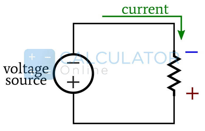
Occurs when electric current flows through a circuit element, decreasing potential along the direction of current.
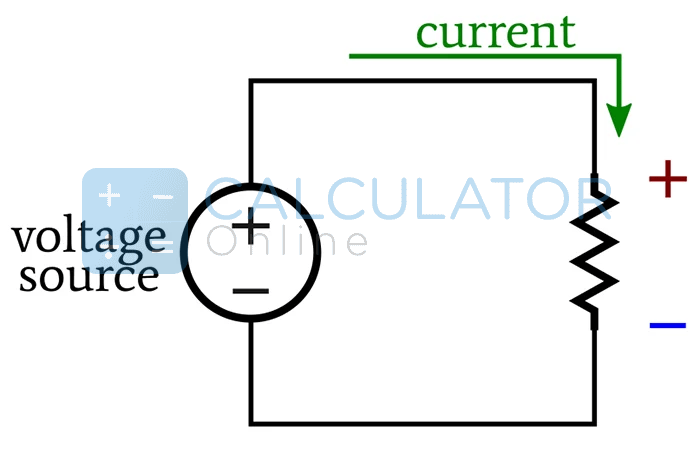
Occurs when current flows opposite to the reference point, creating an apparent increase in potential.
V_drop(V) = I_wire(A) × R_wire(Ω)
V_drop(V) = I_wire(A) × (2 × L(ft) × R_wire(Ω/kft) / 1000)
V_drop(V) = I_wire(A) × (2 × L(m) × R_cable(Ω/km) / 1000)
V_drop(V) = √3 × I_wire(A) × R_wire(Ω)
V_drop(V) = 1.732 × I_wire(A) × (L(ft) × R_wire(Ω/kft) / 1000)
V_drop(V) = 1.732 × I_wire(A) × (L(m) × R_wire(Ω/km) / 1000)
The calculator quickly shows the exact voltage loss across wires for single-phase or three-phase systems.
For wire gauge n:
d_n(in) = 0.005 × 92^((36-n)/39)
In millimeters:
d_n(mm) = 0.127 × 92^((36-n)/39)
Depends on the diameter:
A_n(kcmil) = 1000 × d_n² = 0.025 in² × 92^((36-n)/19.5)
A_n(in²) = (π/4) × d_n² = 0.000019635 in² × 92^((36-n)/19.5)
A_n(mm²) = (π/4) × d_n² = 0.000019635 mm² × 92^((36-n)/19.5)
Resistance based on cross-sectional area:
R_n(Ω/kft) = 0.3048 × 10⁹ × ρ(Ω·m) / (25.4² × A_n(in²))
Voltage drop occurs when the potential at the end of a wire is lower than at the start, resulting in a loss along the conductor.
Yes, voltage drop is proportional to conductor length and resistance. Increasing either increases the voltage drop. Learn more.
The maximum permissible voltage drop for any feeder to the farthest load should not exceed 5% of supply voltage.
| AWG | Diameter | Turns of Cable | Area | Copper Resistance | ||||
|---|---|---|---|---|---|---|---|---|
| inch | mm | per inch | per cm | kcmil | mm² | Ω/km | Ω/1000ft | |
| 0000 (4/0) | 0.4600 | 11.684 | 2.17 | 0.856 | 212 | 107 | 0.1608 | 0.04901 |
| 000 (3/0) | 0.4096 | 10.404 | 2.44 | 0.961 | 168 | 85.0 | 0.2028 | 0.06180 |
| 00 (2/0) | 0.3648 | 9.266 | 2.74 | 1.08 | 133 | 67.4 | 0.2557 | 0.07793 |
Related
Add this calculator to your site.
×Just copy a given code & paste it right now into your website HTML (source) for suitable page.
Preview:


Easter into Action, Save With Satisfaction
UPTO
50 %
OFF
Give Us Your Feedback
Share Result
Voltage Drop Calculator

Links
Home Conversion Calculator About Calculator Online Blog Hire Us Knowledge Base Sitemap Sitemap TwoEmail us at
Contact Us© Copyrights 2026 by Calculator-Online.net